Vehicle Damage Warnings
PRECAUTIONSPrecaution for Supplemental Restraint System (SRS) "AIR BAG" and "SEAT BELT PRE-TENSIONER"
The Supplemental Restraint System such as "AIR BAG" and "SEAT BELT PRE-TENSIONER" used along with a front seat belt, helps to reduce the risk or severity of injury to the driver and front passenger for certain types of collision. This system includes seat belt switch inputs and dual stage front air bag modules. The SRS system uses the seat belt switches to determine the front air bag deployment, and may only deploy one front air bag, depending on the severity of a collision and whether the front occupants are belted or unbelted.
Information necessary to service the system safely is included in the SRS and SB section of this Service Manual.
WARNING:
^ To avoid rendering the SRS inoperative, which could increase the risk of personal injury or death in the event of a collision which would result in air bag inflation, all maintenance must be performed by an authorized NISSAN/INFINITI dealer.
^ Improper maintenance, including incorrect removal and installation of the SRS, can lead to personal injury caused by unintentional activation of the system. For removal of Spiral Cable and Air Bag Module, see the SRS section.
^ Do not use electrical test equipment on any circuit related to the SRS unless instructed to in this Service Manual. SRS wiring harnesses can be identified by yellow and/or orange harnesses or harness connectors.
Precaution Necessary for Steering Wheel Rotation After Battery Disconnect
NOTE:
^ This Procedure is applied only to models with Intelligent Key system and NVIS/IVIS (NISSAN/INFINITI VEHICLE IMMOBILIZER SYSTEM - NATS).
^ Remove and install all control units after disconnecting both battery cables with the ignition knob in the "LOCK" position.
^ Always use CONSULT-III to perform self-diagnosis as a part of each function inspection after finishing work. If DTC is detected, perform trouble diagnosis according to self-diagnostic results.
For models equipped with the Intelligent Key system and NVIS/IVIS, an electrically controlled steering lock mechanism is adopted on the key cylinder.
For this reason, if the battery is disconnected or if the battery is discharged, the steering wheel will lock and steering wheel rotation will become impossible.
If steering wheel rotation is required when battery power is interrupted, follow the procedure below before starting the repair operation.
OPERATION PROCEDURE
1. Connect both battery cables.
NOTE:
Supply power using jumper cables if battery is discharged.
2. Use the Intelligent Key or mechanical key to turn the ignition switch to the "ACC" position. At this time, the steering lock will be released.
3. Disconnect both battery cables. The steering lock will remain released and the steering wheel can be rotated.
4. Perform the necessary repair operation.
5. When the repair work is completed, return the ignition switch to the "LOCK" position before connecting the battery cables. (At this time, the steering lock mechanism will engage.)
6. Perform a self-diagnosis check of all control units using CONSULT-III.
Precaution for On Board Diagnosis (OBD) System of CVT and Engine
The ECM has an on board diagnostic system. It will light up the malfunction indicator lamp (MIL) to warn the driver of a malfunction causing emission deterioration.
CAUTION:
^ Be sure to turn the ignition switch OFF and disconnect the battery cable from the negative terminal before any repair or inspection work. The open/short circuit of related switches, sensors, solenoid valves, etc. will cause the MIL to light up.
^ Be sure to connect and lock the connectors securely after work. A loose (unlocked) connector will cause the MIL to light up due to an open circuit. (Be sure the connector is free from water, grease, dirt, bent terminals, etc.)
^ Be sure to route and secure the harnesses properly after work. Interference of the harness with a bracket, etc. may cause the MIL to light up due to a short circuit.
^ Be sure to connect rubber tubes properly after work. A misconnected or disconnected rubber tube may cause the MIL to light up due to a malfunction of the EVAP system or fuel injection system, etc.
^ Be sure to erase the unnecessary malfunction information (repairs completed) from the TCM and ECM before returning the vehicle to the customer.
Service After Replacing TCM and Transaxle Assembly
SERVICE AFTER REPLACING TCM AND TRANSAXLE ASSEMBLY
Perform the applicable service in the following sheet when replacing TCM or transaxle assembly
CAUTION:
^ Do not start the engine until the service is completed.
^ "TCM-POWER SUPPLY [P1701]" may be indicated soon after replacing TCM or transaxle assembly (after erasing the memory at the pattern B). Restart the self-diagnosis after erasing the self-diagnosis result. Check that no error is detected.
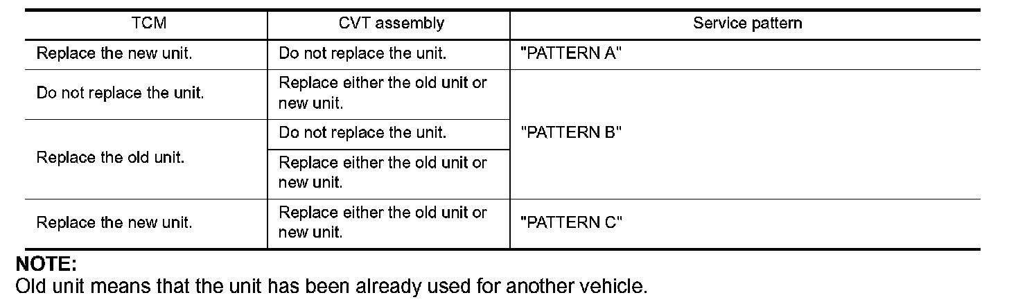
PATTERN A
1. Shift the selector lever to "P" position after replacing TCM. Turn the ignition switch ON.
2. Check that the shift position indicator in the combination meter turns ON (It indicates approximately 1 or 2 seconds after turning the ignition switch ON.)
^ Check the following items if the shift position indicator does not turn ON. Repair or replace the shift position indicator if necessary.
^ The harness between TCM and ROM ASSY in the transaxle assembly is open or short.
^ Cable disconnected, loosen, or bent from the connector housing.
PATTERN B
1. Turn the ignition switch ON after replacing each part.
2. Start engine.
CAUTION:
Do not start the driving.
3. Touch CONSULT-III screen in the order of "DATA MONITOR", and "MAIN SIGNALS".
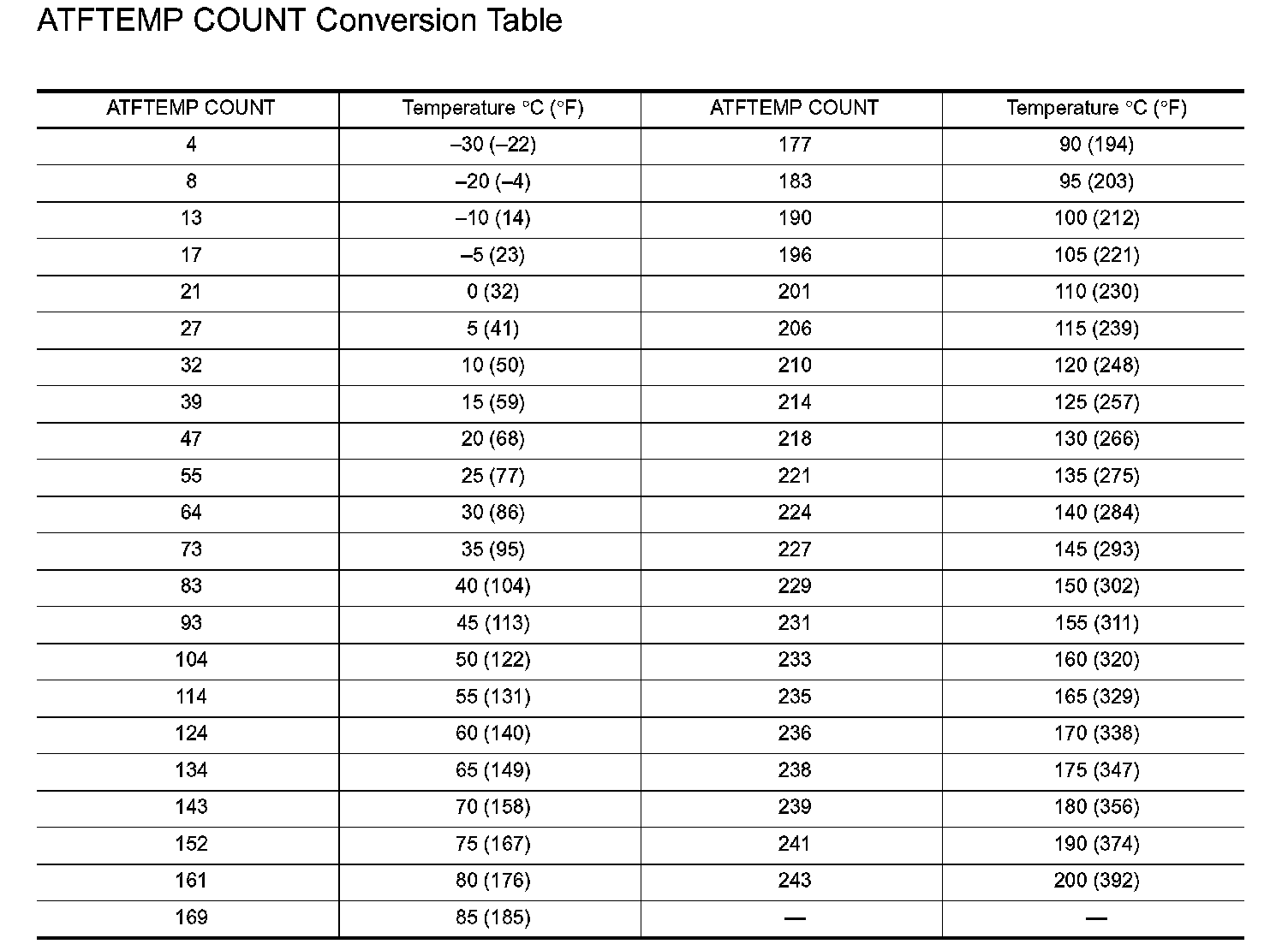
4. Warm up the transaxle assembly until "ATF TEMP COUNT" indicates 47 [approximately 20 degrees C (68 degrees F)] or more. Turn the ignition switch OFF.
5. Turn the ignition switch ON.
CAUTION:
Do not start engine.
6. Select "SELF-DIAG RESULTS".
7. Shift the selector lever to "R" position.
8. Depress slightly the accelerator pedal (Pedal angle: 2/8) while depressing the brake pedal.
9. Perform "ERASE".
10. Shift the selector lever to "R" position after replacing TCM. Turn the ignition switch OFF.
11. Wait approximately 10 minutes after turning the ignition switch OFF.
12. Turn the ignition switch ON while shifting the selector lever to "R" position.
CAUTION:
Do not start engine.
13. Select "Special function".
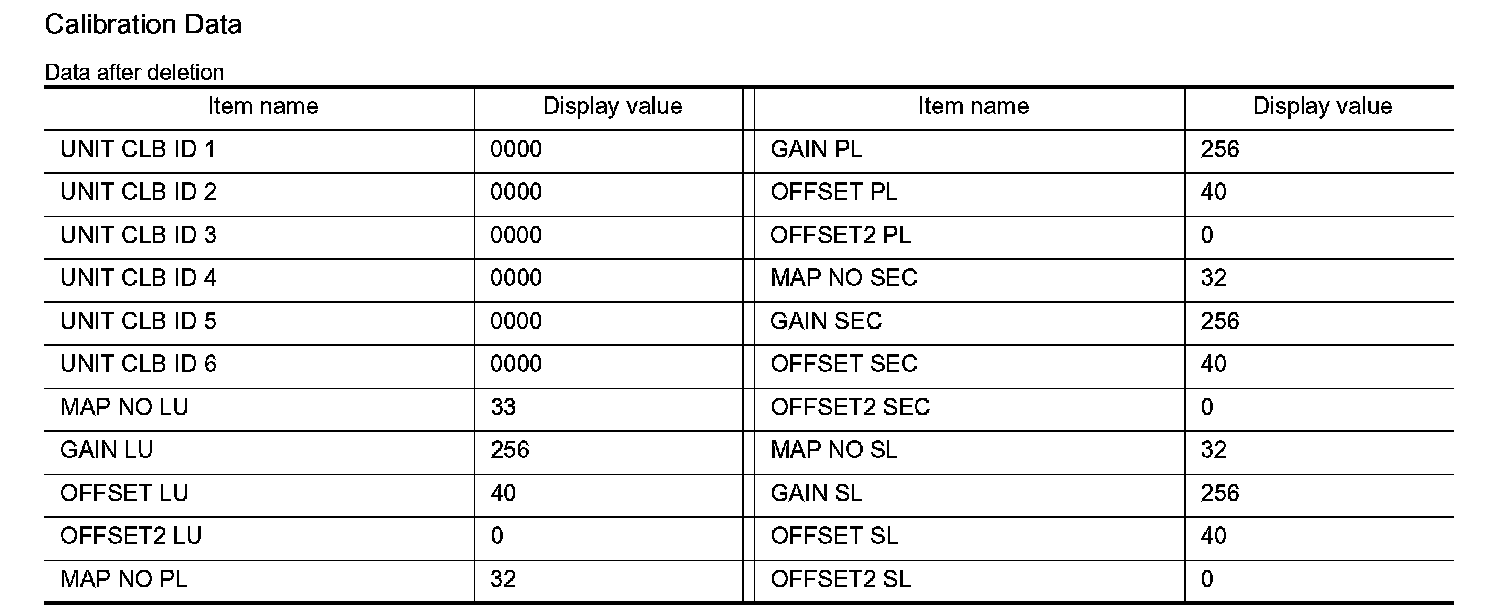
14. Check that the value on "CALIBRATION DATA" is same as the data after erasing "Calibration Data".
^ Restart the procedure from step 3 if the values are not same.
15. Shift the selector lever to "P" position.
16. Check that the shift position indicator in the combination meter turns ON (It indicates approximately 1 or 2 seconds after shifting the selector lever to "P" position.)
^ Check the following items if the shift position indicator does not turn ON. Repair or replace the shift position indicator if necessary.
^ The harness between TCM and ROM ASSY in the transaxle assembly is open or short.
^ Cable disconnected, loosen, or bent from the connector housing.
^ Power supply and ground of TCM. Refer to CVT-121. P1701
Calibration Data
PATTERN C
1. Replace the transaxle assembly first, and then replace TCM.
2. Perform the service of "PATTERN A".
(Perform the service of "PATTERN B" if TCM is replaced first.)
Removal and Installation Procedure for CVT Unit Connector
REMOVAL
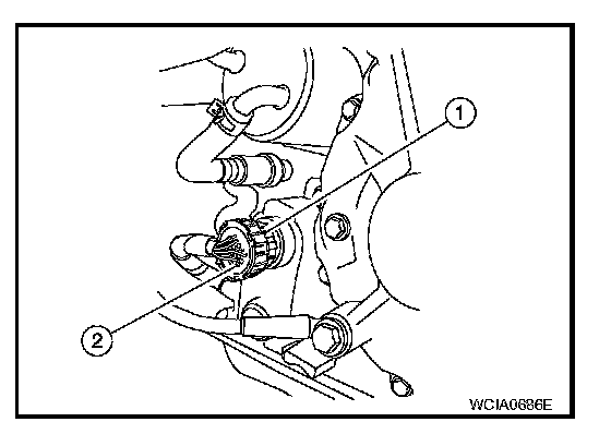
Rotate bayonet ring (1) counterclockwise, pull out CVT unit harness connector (2) outward and disconnect it.
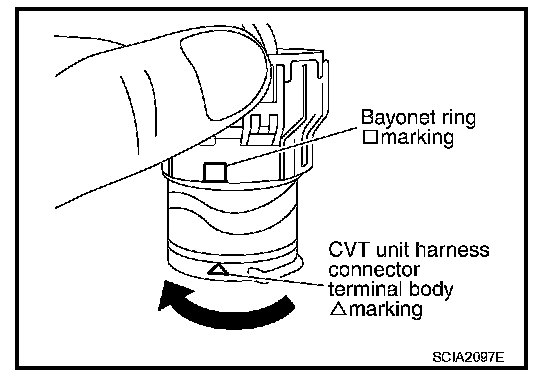
1. Align CVT unit harness connector terminal body marking with bayonet ring marking, insert CVT unit harness connector, and then rotate bayonet ring clockwise.
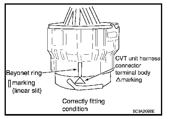
2. Rotate bayonet ring clockwise until CVT unit harness connector terminal body marking is aligned with the bayonet ring marking (linear slit) as shown.
CAUTION:

^ Securely align CVT unit harness connector terminal body marking with bayonet ring marking (linear slit). Do not make a half fit condition as shown.
^ Do not mistake the bayonet ring marking (linear slit) for other dent portion.
Precaution
NOTE:
If any malfunction occurs in the RE0F10A model transaxle, replace the entire transaxle assembly.
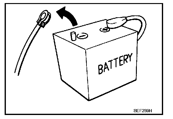
^ Before connecting or disconnecting the TCM harness connector, turn ignition switch OFF and disconnect negative battery cable. Because battery voltage is applied to TCM even if ignition switch is turned OFF.

^ When connecting or disconnecting pin connectors into or from TCM, take care not to damage pin terminals (bend or break).
When connecting pin connectors make sure that there are not any bends or breaks on TCM pin terminal.
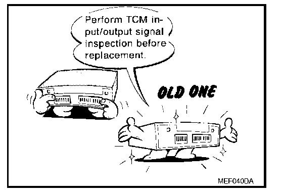
^ Before replacing TCM, perform TCM input/output signal inspection and make sure whether TCM functions properly or not. CVT-44, "TCM Input/Output Signal Reference Value". Pinout Values and Diagnostic Parameters
^ After performing each TROUBLE DIAGNOSIS, perform "DTC Confirmation Procedure".
If the repair is completed the DTC should not be displayed in the "DTC Confirmation Procedure".
^ Always use the specified brand of CVT fluid.
^ Use lint-free paper, not cloth rags, during work.
^ After replacing the CVT fluid, dispose of the waste oil using the methods prescribed by law, ordinance, etc.
^ Before proceeding with disassembly, thoroughly clean the outside of the transaxle. It is important to prevent the internal parts from becoming contaminated by dirt or other foreign matter.
^ Disassembly should be done in a clean work area.
^ Place disassembled parts in order for easier and proper assembly
^ All parts should be carefully cleaned with a general purpose, non-flammable solvent before inspection or reassembly.
^ Gaskets, seals and O-rings should be replaced.
^ It is very important to perform functional tests whenever they are indicated.
^ Before assembly, apply a coat of recommended ATF to all parts. Apply petroleum jelly to protect O-rings and seals.
^ Extreme care should be taken to avoid damage to O-rings, seals and gaskets when assembling. Clean or replace CVT fluid cooler if excessive foreign material is found in oil pan.
^ When the CVT drain plug is removed, only some of the fluid is drained. Old CVT fluid will remain in torque converter and CVT fluid cooling system.
Always follow the procedures under "Changing CVT Fluid" in the CVT section when changing CVT fluid. Refer to CVT-14, "Checking CVT Fluid". Changing CVT Fluid
TORQUE CONVERTER SERVICE
The torque converter should be replaced under any of the following conditions:
^ External leaks in the hub weld area.
^ Converter hub is scored or damaged.
^ Converter pilot is broken, damaged or fits poorly into crankshaft.
^ Steel particles are found after flushing the cooler and cooler lines.
^ Pump is damaged or steel particles are found in the converter.
^ Vehicle has TCC shudder and/or no TCC apply Replace only after all hydraulic and electrical diagnoses have been made. (Converter clutch material may be glazed.)
^ Converter is contaminated with engine coolant containing antifreeze.
^ Internal malfunction of stator roller clutch.
^ Heavy clutch debris due to overheating (blue converter).
^ Steel particles or clutch lining material found in fluid filter or on magnet when no internal parts in unit are worn or damaged - indicates that lining material came from converter.
The torque converter should not be replaced if:
^ The fluid has an odor, is discolored, and there is no evidence of metal or clutch facing particles.
^ The threads in one or more of the converter bolt holes are damaged.
^ CVT malfunction did not display evidence of damaged or worn internal parts, steel particles or clutch plate lining material in unit and inside the fluid filter.
^ Vehicle has been exposed to high mileage (only). The exception may be where the torque converter clutch dampener plate lining has seen excess wear by vehicles operated in heavy and/or constant traffic such as taxi, delivery or police use.
Service Notice or Precaution
OBD-II SELF-DIAGNOSIS
^ CVT self-diagnosis is performed by the TCM in combination with the ECM. The results can be read through the blinking pattern of the malfunction indicator lamp (MIL). Refer to the table on CVT-46, "CONSULT-III Function (TRANSMISSION)" for the indicator used to display each self-diagnostic result. Consult-III Function (Transmission)
^ The self-diagnostic results indicated by the MIL are automatically stored in both the ECM and TCM memories.
Always perform the procedure on CVT-24, "OBD-II Diagnostic Trouble Code (DTC)" to complete the repair and avoid unnecessary blinking of the MIL. Reading and Clearing Diagnostic Trouble Codes
^ Certain systems and components, especially those related to OBD, may use the new style slide-locking type harness connector.
ATFTEMP COUNT Conversion Table