Right Hand Drive
Exterior Lamps: Brake Switch:
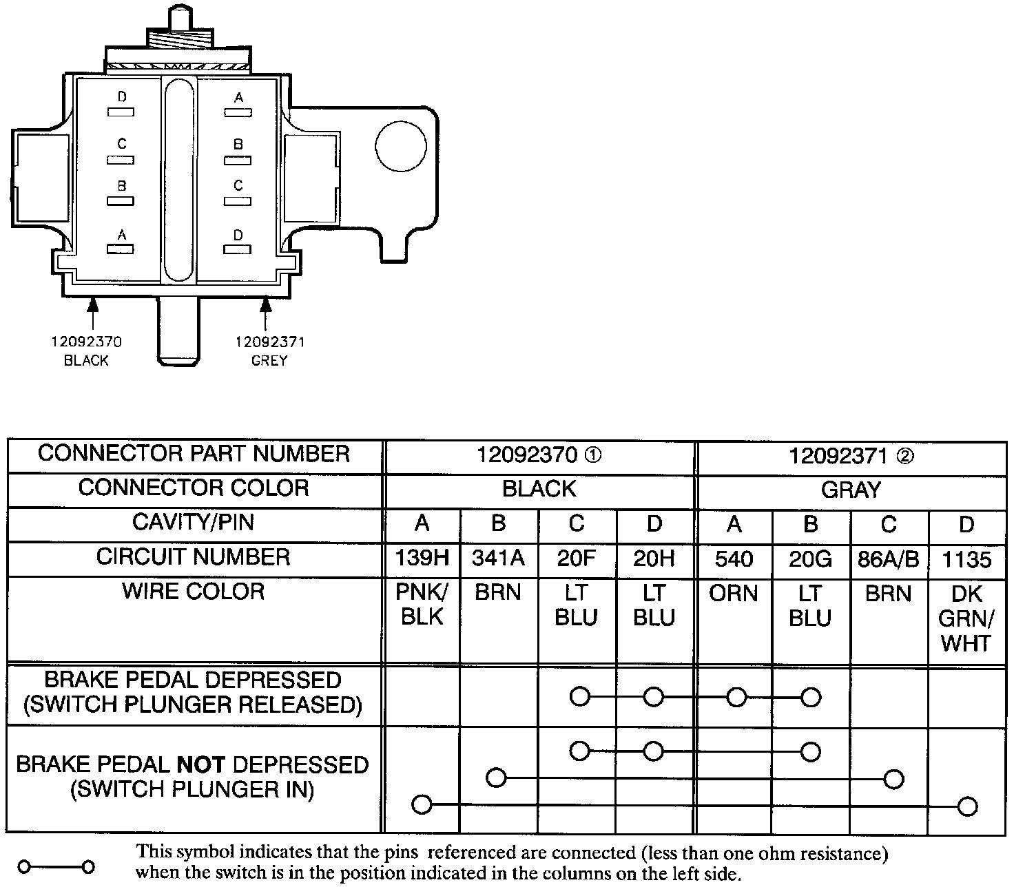
BRAKE SWITCH
Check connections and terminals for damage, tightness, or corrosion.
Check switch resistance pin A (gray connector) to pin C or D (black connector).
Switch resistance: Open when brake not depressed. Less than one ohm when brake depressed.
Repair/replace as needed.
If this component is good go to the next item indicated on the chart.
TURN HAZARD RELAYS (RELAY #1, RELAY #2)
Location: Taped to I/P harness at lower left corner of HVAC module near accelerator pedal.
There are two Turn/Hazard relays used for hazard lamp operation.
The turn hazard relays are interchangeable with each other, but not with any other relay on the vehicle.
An open in Relay #2 could cause the turn signal lamps to be inoperative.
If turn lamps are inoperative, substitute relay #1 for relay #2, and see if problem is corrected.
Repair and replace as needed.
REAR TAIL LAMP ASSEMBLIES
Check connections and terminals for damage, tightness, or corrosion.
Check resistance through the bulb sockets.
Repair/replace as needed.
FRONT PARK/TURN LAMP ASSEMBLIES
Check connections and terminals for damage, tightness, or corrosion.
Check resistance through the bulb sockets.
Repair/replace as needed.
TURN/HAZARD SWITCH
Refer to Turn Signals/Combination Switch for Lever Combination Switch (LCS) testing. Turn Signal Switch
Repair/replace as needed.
BULBS
Check connections and terminals for damage, tightness, or corrosion.
Visually inspect the bulb. Check the resistance through the bulb.
Repair/replace as needed.
I/P CLUSTER
Refer to Instrument Panel for diagnostic information, and removal and installation procedures for internal cluster components. Instrument Panel, Gauges and Warning Indicators
CENTER HIGH MOUNT STOP LAMP
Check connections and terminals for damage, tightness, or corrosion.
Check resistance through the bulb sockets.
Repair/replace as needed.
Flasher Module:
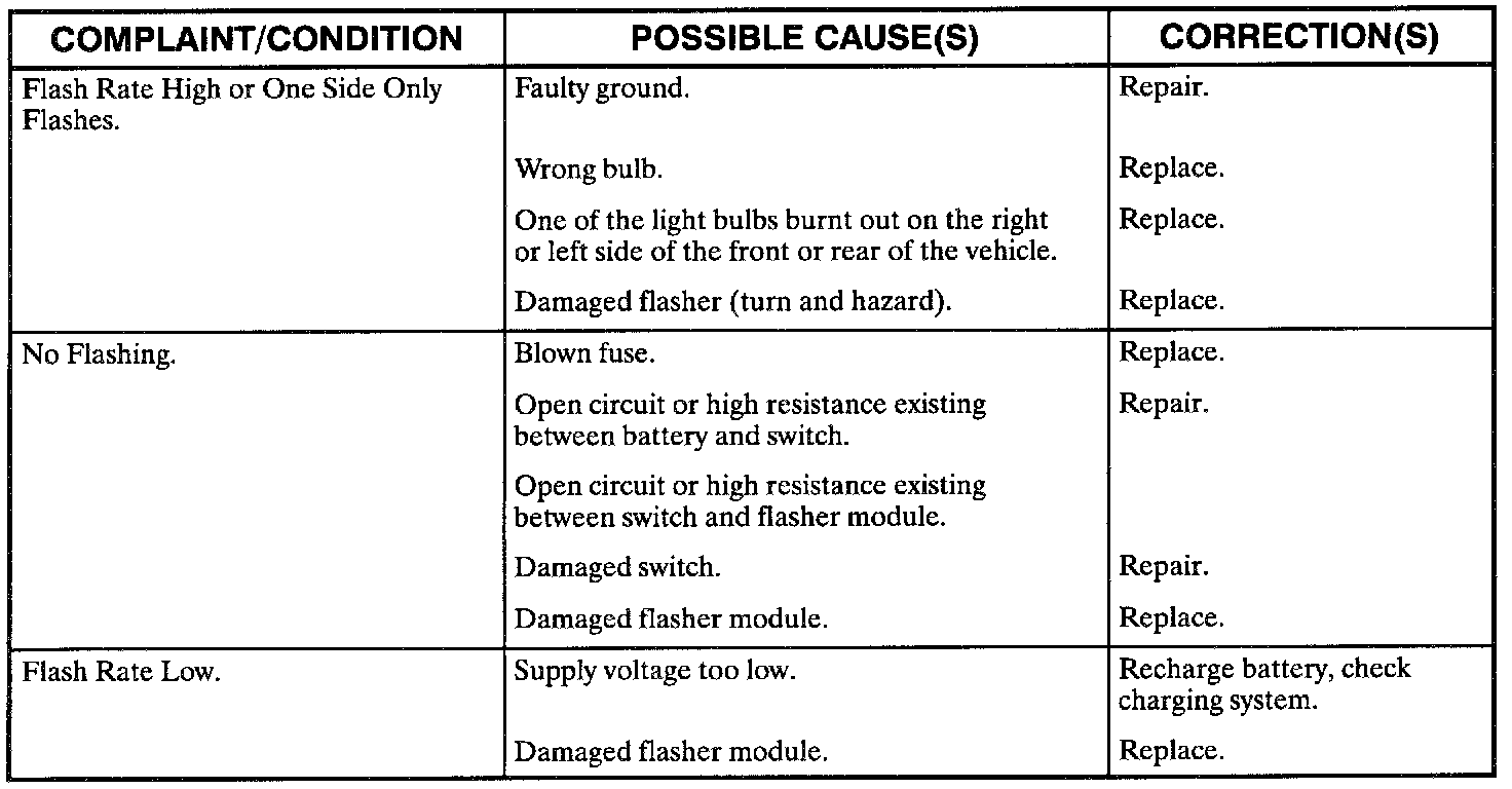
FLASHER MODULE