Brake Pressure Hold Valve: Service and Repair
Fig. 16 Hill Holder (PHV) Valve:

Fig. 17 Hill Holder Installation:
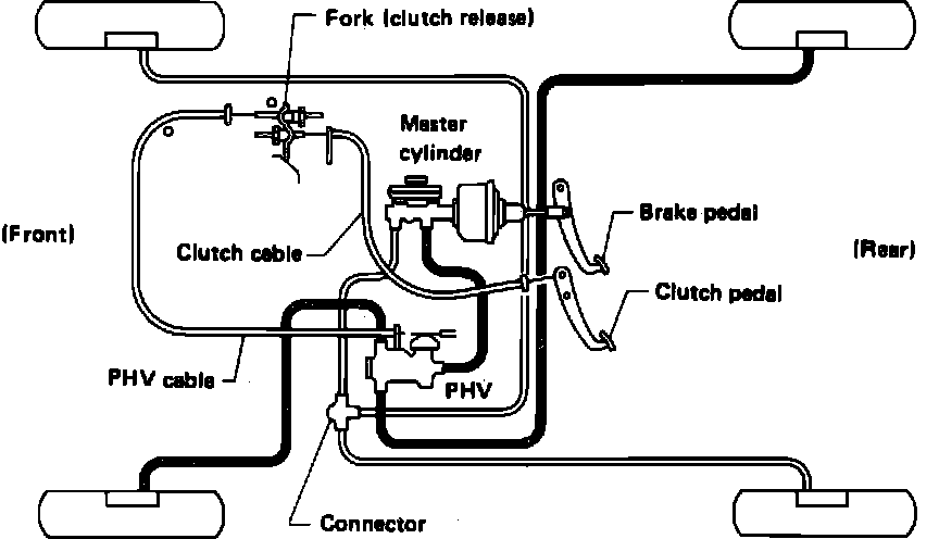
Fig. 18 Hill Holder Activated:

Fig. 19 Hill Holder Deactivated:

The Hill holder is essentially a Pressure Hold Valve (PHV), Fig. 16, built into one brake circuit, that maintains hydraulic pressure in the brake circuit when the vehicle is facing uphill and the clutch pedal is depressed, Fig. 17.
The PHV lever, Fig. 16, is connected through a linkage to the clutch pedal and controlled by a camshaft which provides the motion to the PHV driveshaft. The PHV driveshaft controls the clearance between the PHV inertia controlled ball and seal.
When the clutch pedal is depressed, the PHV driveshaft is pulled into the seal, allowing the ball free movement. If the vehicle is facing uphill, inertia will cause the ball to roll onto the seal, Fig. 18, thereby holding hydraulic pressure. When the clutch is released, Fig. 19, the driveshaft is forced into the ball chamber, unsealing the ball and releasing hydraulic pressure.
REMOVAL
1. Drain primary side of master cylinder.
2. Remove cable adjusting nut and clamp from clutch release bearing fork, then disconnect cable from engine bracket.
3. Remove cable from PHV.
4. Separate connector bracket from PHV, then remove brake lines using a suitable flare wrench.
5. Remove PHV bracket to frame retaining bolts and the PHV. Do not allow any dirt to enter PHV.
INSPECTION
1. Inspect PHV cable boots and outer casing for damage, replace as necessary.
2. Inspect PHV cable inner core for corrosion and wear, replace as necessary.
3. Inspect PHV return spring for damage or corrosion.
4. Tilt PHV assembly and listen for ball rolling to ensure free operation.
5. Operate lever to ensure smooth operation. Do not attempt to disassemble PHV. If unit is defective, it should be replaced.
INSTALLATION
To install, reverse removal procedure, noting the following:
1. Apply lubricant to hooked portion of return spring, cable end of lever and cable end at clutch release bearing fork.
2. Bleed brakes after installation.